
VLAN Bridging in Mobility Express using RAP and MAP
- #wireless
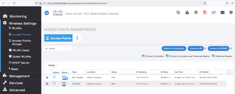
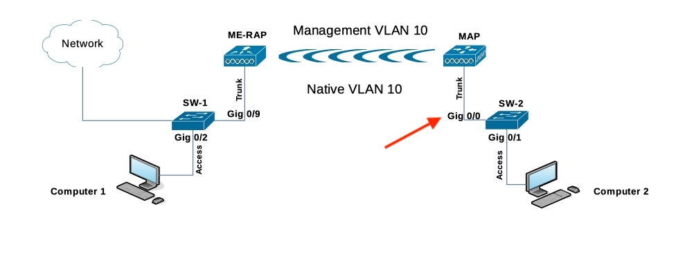
I won’t covert the initial ME configuration and the MAP joining to the controller (I supposed that you have the point to point up and running) as shown the image:
You can follow this link to convert the ME, and do the day zero config, this other link will help you for the point to point link creation.
Components Used
- Computer 1 (Wired to SW1)
- Computer 2 (Wired to SW2)
- 2 Cisco Catalyst Switches (SW1 and SW2)
- 1542I ME WLC + RAP (Version 8.10.151.0)
- 1542I CAPWAP > MAP
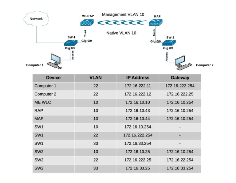
Topology Implemented
I performed a factory reset in the APs prior starting this lab, from the Mobility Express AP initial configuration wizard, I set the internal AP to flex+Bridge mode [yes] [NO]: yes
In case that you missed the flex+bridge setting, you can enable it running the following command in the RAP, you can also run the command in the MAP after the joining process.
RAP# capwap ap mode flex-bridgeA quick recap to get to the internal AP in your ME WLC connect a console cable to the physical device, and run;
(Cisco Controller) > apciscoshell(It’s no possible to run that command via SSH or Telnet)
Configuration
Switch configuration
Switch ports where computers are connected are configured as access ports with VLAN 22:
SW1(config)#interface gigabitEthernet 0/2
SW1(config-if)#switchport mode access
SW1(config-if)#switchport access vlan 22
SW1(config-if)#no shutdown
SW1(config-if)#exit

SW2(config)#interface gigabitEthernet 0/1
SW2(config-if)#switchport mode access
SW2(config-if)#switchport access vlan 22
SW2(config-if)#no shutdown
SW2(config-if)#exit
The Switch ports where APs are connected will be in trunk mode with the native VLAN set to 10:
SW1#configure terminal
SW1(config)#interface gigabitEthernet 0/9
SW1(config-if)#switchport mode trunk
SW1(config-if)#switchport trunk native vlan 10
SW1(config-if)#switchport trunk allowed vlan 10,22,33
SW1(config-if)#no shutdown
SW1(config-if)#end

SW2#configure terminal
Enter configuration commands, one per line.  End with CNTL/Z.
SW2(config)#interface gigabitEthernet 0/0
SW2(config-if)#switchport mode trunk
SW2(config-if)#switchport trunk native vlan 10
SW2(config-if)#switchport trunk allowed vlan 10,22,33
SW2(config-if)#no shutdown
SW2(config-if)#end
Computers configuration
Computer 1
IP ADDR 172.16.222.11/24
GW 172.16.222.254

Computer 2
IP ADDR 172.16.222.12/24
GW 172.16.222.25
ME WLC and AP IP Configuration
(Cisco Controller) >show interface summary


 Number of Interfaces.......................... 2

Interface Name                   Port Vlan Id  IP Address      Type    Ap Mgr Guest
-------------------------------- ---- -------- --------------- ------- ------ -----
management                       1    untagged 172.16.10.10    Static  Yes    N/A
virtual                          N/A  N/A      192.0.2.1       Static  No     N/A
RAP#show ip interface brief
Interface IP-Address Method Status Protocol Speed Duplex
wired0 172.16.10.43 DHCP up up 1000 full
auxiliary-client unassigned unset up up n/a n/a
wifi0 n/a n/a up up n/a n/a
wifi1 n/a n/a up up n/a n/aMAP#show ip int brief
Interface IP-Address Method Status Protocol Speed Duplex
wired0 172.16.10.44 DHCP up up 100 full
auxiliary-client unassigned unset up up n/a n/a
wifi0 n/a n/a up up n/a n/a
wifi1 n/a n/a up up n/a n/aEthernet Bridging
In order for wired clients behind the MAP send traffic over the mesh link, Ethernet Bridging needs to be enabled on the MAP under Wireless Settings > Access Points > MAP > Mesh:
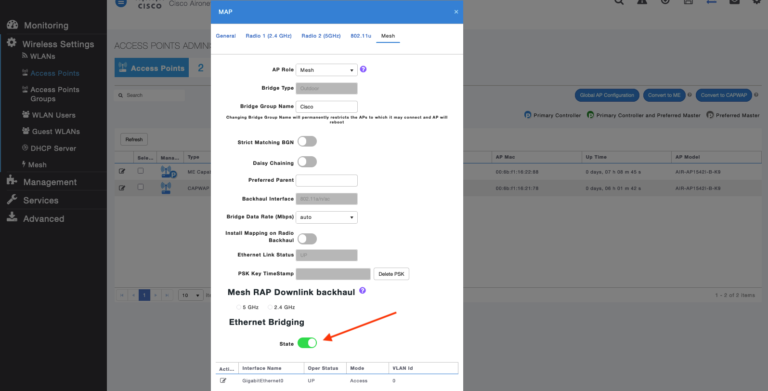
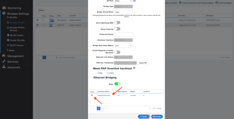
Notice that we have the physical interface at the bottom of the page, if we click on edit, it will open the interface options:
Now, if we try to change the interface mode from Access to Trunk, adding the native VLAN, and the VLANs Id desire you will get an error:
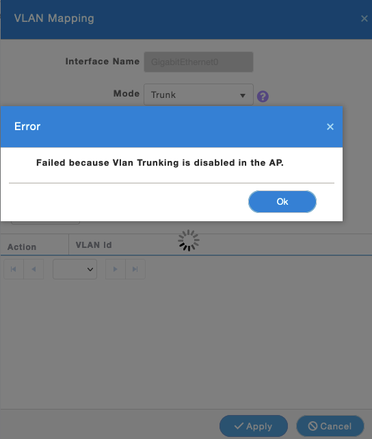
We need to run one CLI commands to fix this, for now let’s continue changing another needed GUI setting.
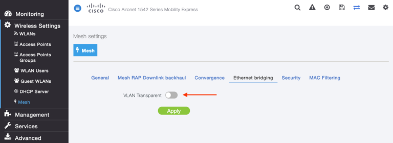
The VLAN mode must be set as non-VLAN transparent (global mesh parameter). VLAN transparent is enabled by default, to set as non-VLAN transparent, you must unselect the VLAN transparent option in the Wireless > Mesh > Ethernet Bridging:
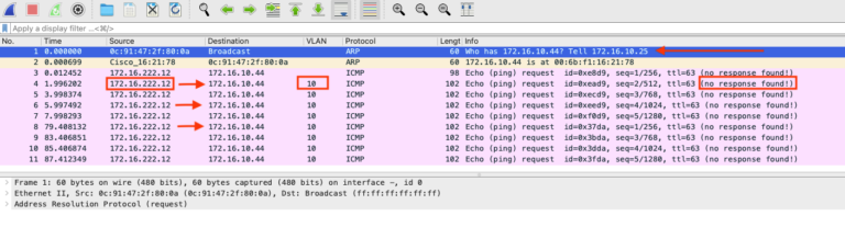
Let’s see the traffic flow making ICMP from Computer 2, let’s recall the Computer 2 belongs to VLAN 22.
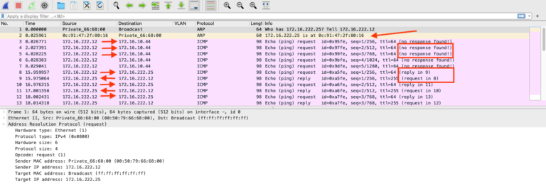
ARP is working as expected, and the computer has bidirectional communication to its gateway 172.16.222.25 (SW2), but when computer pings the MAP IP address 172.16.10.44 the traffic is in one direction.
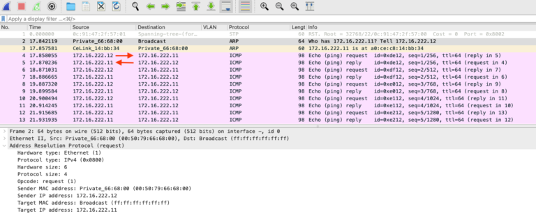
Let’s see another capture in the upstream device (which is the SW2) pointing to the MAP AP, the red arrow is our target interface:
So, we can see the ARP replied coming from the MAP, and the ICMP going out of the SW2, the destination the MAP IP, the traffic is getting tag on the VLAN 10 which tell us the SW2 is doing the job tagging traffic, but there is no replies getting back from MAP.
Converting from access to trunk the MAP physical port
As I said earlier, we need to run a CLI commands to make the VLAN mapping works, from the ME WLC run:
(Cisco Controller)> config flexconnect group default-flexgroup vlan enableLet’s remember the ME by nature works in flexconnect, and globally we are enabling multiple VLANs support.
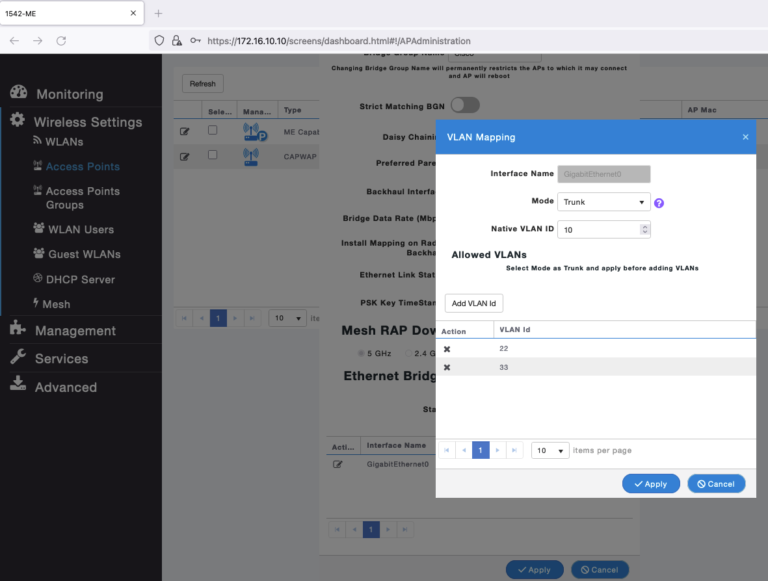
Now, if we go to the ME WLC GUI > Wireless Settings > Access Points > select the MAP and click edit > Mesh > Edit Interface we should be able to change the mode from Access to Trunk.

First step, change the Mode to trunk and add the Native VLAN ID, the native VLAN id must match with the native VLAN of your switch, hit apply.
Second step, add the VLAN ids needed, in my case 22 and 33, hit apply.
If you like the CLI way, you can go to the ME WLC CLI and run the following to accomplish the above;
(Cisco Controller) >config ap ethernet 0 mode trunk enable <AP Name> native-vlan <VLAN ID>

(Cisco Controller) >config ap ethernet 0 mode trunk add <ap name> <vlan ID> >>>>> Up to 16 VLANs <<<<<<Let’s see how this work!!!
From Computer 2, I will start the ICMP traffic again , but now I will ping the Computer 1 IP 172.16.222.11, the traffic should cross the wireless link:
In fact we can see the Computer 2 requesting ARP to know the physical location of Computer 1, and the ICMP traffic is bidirectional, now let’s see the tagging from the SW2 side:
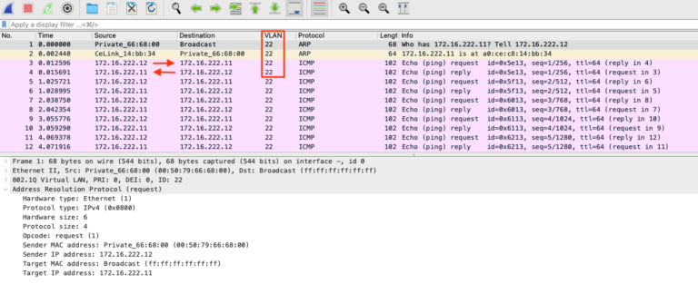
Sweet, it’s the same traffic pattern, but now it includes the VLAN tagging (which is the expected scenario).
Lastly, I will run a round robin of ICMP from Computer 2, I will capture from SW2 to keep it simple and familiar:
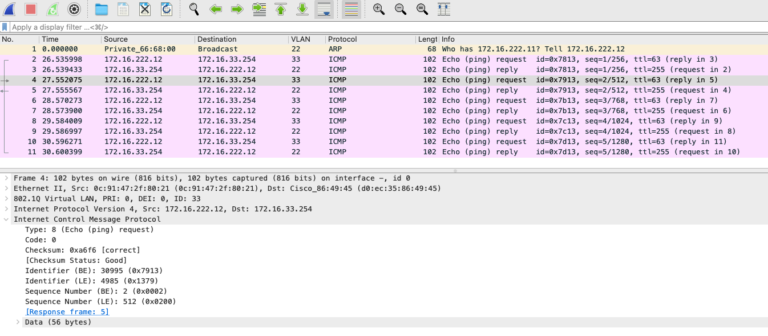
SW1 has a SVI on VLAN 33 IP 172.16.33.254, now I can ping any device in VLAN 10, 22, and 33 from both ends.
The point to point VLAN mapping is working as expected!
I hope this post guide you and serve as your reference, I created this post because the documentation that I found is no very clear.
Be Safe!